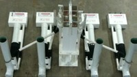
This section covers details for implementation of Cuebox arrangements. Get familiar with Flout Basics before proceeding.
LOCATION IN CHAMBER:
The Cuebox™ may be anywhere there is room in the chamber but some locations are better than others. Near the common outlet wall is the best, with the Cuebox between the vents, near the center of the array. This minimizes the length of the trigger tubes between the CueBox and Flouts. If the Flouts exit multiple walls, position the Cuebox at the center. >Example...
CHAMBER LENGTH:
A Cuebox Flout is 3 inches longer than a regular Flout. The minimum chamber length for 3" Flouts with internal venting is DD plus 27 inches. With external venting, it's 15 inches.
CHAMBER HEIGHT and ACCESS:
The overall height to the top of the CueBox is 13" above the maximum liquid level. Provide enough headroom either under the chamber lid or within the riser. Access directly above the Cuebox with clearence all around is mandatory. The service handles should extend up to a reachable height under the access cover. >Example...
MOUNTING:
CueBoxes may be bolted to the chamber floor or weighted down with solid concrete blocks. The latter is the method of choice for retrofit situations. >Examples...
TRIGGER TUBING: VERY IMPORTANT!
Trigger tubes must be positioned carefully. They must have clearance to move up and down. Do not allow Flouts to contact trigger tubes. The trigger manifolds must be able to rotate freely so the floats do not bind. >Learn more...
DIFFERENT DRAWDOWNS:
Different DD Flouts can operate in a common chamber. The Cuebox SET would be to the deepest Flout plus any shims. >Example...
MULTIPLE TRIGGERING:
One Flout may be triggered more than once per cycle by combining the trigger tubes from two or more cells. A 3 cell CueBox could trigger Flout 1 one time and Flout 2 twice per cycle. Combined trigger manifolds should be on the same side as the Flout. Triggering of two of more Flouts from one trigger >Example under construction...
FLOUT TYPE MIX:
Single and Multi Flouts of different pipe size may be combined in one system. >Example under construction...
SWITCHING: Floats within the Cuebox may be turned to redirect the control ball to shut-off certain Flouts. >Example...
THE CUEBOX™ NUMBERING SYSTEM:
The "SET": The Cuebox order number is QB followed by the number of trigger manifolds, followed by the "SET" which is the Flout turn-on depth in inches. The SET is drawdown (DD)+ shut-off depth of the Flouts (4" for 3" pipe Flouts and 5" for 4" pipe Flouts)+ any shim height, measured to the center of the H fitting. The standard set for a Cuebox is 14". For deeper sets, an extension shim or table will be supplied. For a set of less, units are trimmed up to 4" for a minimum set of 10" for a 6"DD 3" pipe Flout arrangement. See Basic Requirements for minimum Flout drawdowns..
Example: Three 3" Flouts with 24 inches of drawdown (DD) on 4" shims are required. The SET would be the shut off depth of 4 inches + 24" DD + 4" shim for 32" total. A 14" standard SET Cuebox and an 18" extension table would be supplied. The number would be QB-3-32. The overall height is 32+13=45 inches.
Example: Five 4" Flouts with 17 inches of drawdown (DD) without shims are required. The SET would be the shut off depth of 5 inches + 17" DD for a 22 inche total. A 14" standard SET Cuebox and a 8" extension table would be supplied. The number would be QB-5-22. The overall height is 22+13=35 inches.
Example: Four 3" Flouts with 8 inches (DD) without shims are required. The SET would be the shut off depth of 4 inches + 8" DD for a 12 inch total. A 14" standard SET Cuebox would be trimmed 2". The number would be QB-4-12. The overall height is 8+13=21 inches.
Example: If number is QB-2-21 ...It's a Cuebox with two outputs with a 21 inch SET.
Example: If number is QB-6-14... It's a Cuebox with 6 outputs with a 14 inch SET.
