
This section covers details for implementation of Alternator arrangements. Get familiar with Flout Basics before proceeding.
Alternating Flouts must have at least 15 inches of drawdown
A 3" Single Flout/ Alternator arrangement needs a chamber at least 24" wide. The minimum length of the chamber is the drawdown in inches x 1.2 plus 24 inches. The ceiling height should be at least 8 inches above maximum liquid height.
ACCESS AND LOCATION IN CHAMBER:
Provide an access cover directly above the vents and alternator device. Position the inlet pipe away from the Flouts in their lower position. If the inlets do end close to the Flouts, provide a downpipe to shield them from the flow. Extend the downpipe to the shut-off depth. When pumping to the chamber, drill a small hole in the downpipe above the water line to stop back-siphoning.
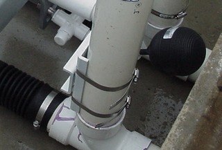
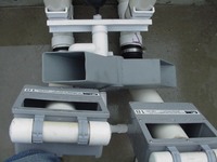
MOUNTING:
The Alternator device straps to the vents. THE VERTICAL VENTS MUST BE 12" ON CENTER. Make sure the control float clears the wall. Vents are supplied with proper length stubs .
ALTERNATOR NUMBERING: Use a standard Flout ordering number followed by "A"
METHOD OF RESTING FIELDS (SHUT ONE OFF):
The Alternating device can be shut off, forcing all dosing to one disposal field. All that is required is a light weight and durable rope with a wire hook to lift Alternator's control float. Tying off the rope in the manhole keeps the bucket to one side. Releasing the rope resumes alternating. Tying off the rope with the bucket to the other side doses the other outlet.